Wireless Site Infrastructure
Low Loss Cables & Pigtails
At RfWeL we offer both standard stock and custom built low loss and ultra low loss cables for your signal transmission needs. For RF installations requiring coaxial cables, it is usually preferrable that you maintain the attenuation loss as low as possible. Cable runs for RF installations should be maintained as short as possible to ensure minimal signal loss.
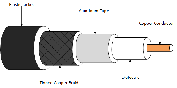
Cross-Section of a Coaxial Cable
Typically, attenuation loss is a factor of cable length and frequency of operation. The longer the cable run, the higher the loss and the higher the frequency of operation the higher the attenuation. It is therefore advisable to use the 400 and 600 series cable for runs greater than 100ft.
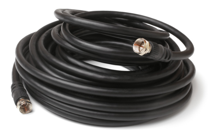
Image of Coaxial Cable Roll
Below is a table showing typical attenuation loss for some common types of coaxial cables:
|
200 Series Coaxial Cable Typical Attenuation in dB | |||||||||||||||
|---|---|---|---|---|---|---|---|---|---|---|---|---|---|---|---|
| Frequency (Application) |
10 ft |
20 ft |
50 ft |
||||||||||||
| Low-Band Cellular (600MHz, Band 71) |
0.9 | 1.8 | 4.5 | ||||||||||||
| 900MHz ISM (LoRaWAN, Helium, etc.) | 1.2 | 2.2 | 5.5 | ||||||||||||
| Mid-Band Cellular (1900Mhz PCS) |
1.7 | 3.3 | 8.1 | ||||||||||||
| 2.4GHz (WiFi 4) |
1.9 | 3.7 | 9.2 | ||||||||||||
| 3.5Ghz (C-Band, CBRS) | 2.3 | 4.5 | 11.2 | ||||||||||||
| 5GHz (Wi-Fi 5/6) | 2.8 | 5.5 | 13.5 | ||||||||||||
| 6Ghz (Wi-Fi 6E) | 3.1 | 6.1 | 14.9 | ||||||||||||
|
400 Series Coaxial Cable Typical Attenuation in dB | |||||||||||||
|---|---|---|---|---|---|---|---|---|---|---|---|---|---|
| Frequency (Application) |
20 ft |
50 ft |
100 ft |
||||||||||
| Low-Band Cellular (600MHz, Band 71) | 0.7 | 1.8 | 3.5 | ||||||||||
| 900MHz ISM (LoRaWAN, Helium, etc.) | 0.9 | 2.2 | 4.4 | ||||||||||
| Mid-Band Cellular (1900Mhz PCS) |
1.4 | 3.3 | 6.5 | ||||||||||
| 2.4GHz (WiFi 4) |
1.6 | 3.7 | 7.4 | ||||||||||
| 3.5Ghz (C-Band, CBRS) | 1.9 | 4.6 | 9.1 | ||||||||||
| 5GHz (Wi-Fi 5/6) | 2.3 | 5.6 | 11.1 | ||||||||||
| 6Ghz (Wi-Fi 6E) | 2.6 | 6.2 | 12.3 | ||||||||||
|
600 Series Coaxial Cable Typical Attenuation in dB | |||||||||||||
|---|---|---|---|---|---|---|---|---|---|---|---|---|---|
| Frequency (Application) |
100 ft |
150 ft |
200 ft |
||||||||||
| Low-Band Cellular (600MHz, Band 71) |
2.3 | 3.4 | 4.5 | ||||||||||
| 900MHz ISM (LoRaWAN, Helium, etc.) | 2.8 | 4.2 | 5.6 | ||||||||||
| Mid-Band Cellular (1900Mhz PCS) |
4.3 | 6.3 | 8.4 | ||||||||||
| 2.4GHz (WiFi 4) |
4.9 | 7.2 | 9.6 | ||||||||||
| 3.5Ghz (C-Band, CBRS) | 6.0 | 9.0 | 12.0 | ||||||||||
| 5GHz (Wi-Fi 5/6) | 7.4 | 11.1 | 14.8 | ||||||||||
| 6Ghz (Wi-Fi 6E) | 8.3 | 12.4 | 16.5 | ||||||||||
Consider the following when choosing a Low-Loss/ Ultra Low-Loss Cable:
- Characteristic impedance (Should match with impedance of other network components).
- Frequency of application as it determines the attenuation of your signal, the higher the frequency the higher the attenuation.
- Operational power handling capabilities
- Voltage Standing Wave Ratio (VSWR)
- Environmental conditions (Determines the level of cable flexibility, shielding & cladding material etc.)
- Noise handling (The symmetry of signal and returning current carrying conductors cancels, to first order, all effects of external electromagnetic fields. Any residual susceptibility in a coaxial cable results from imperfections in its shield)
- Phase Delay (Time delay for each frequency component)
RfWeL stocks a wide variety of low loss and ultra low loss cables for your diverse needs. Contact our Wireless Communication Specialists here to help with your cable/ pigtail selection.
View 600-series low-loss cables: 
View 400-series low-loss cables: 
View device connectors and adapters: 
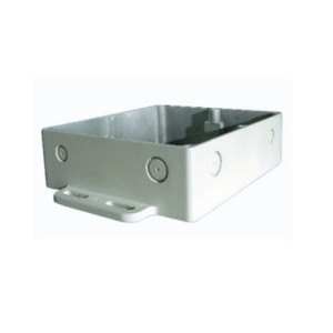
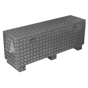
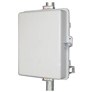
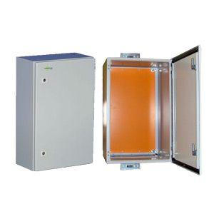
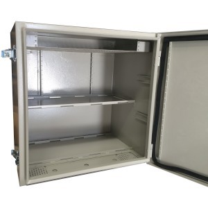
Radio Equipment Enclosures
|
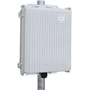
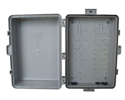
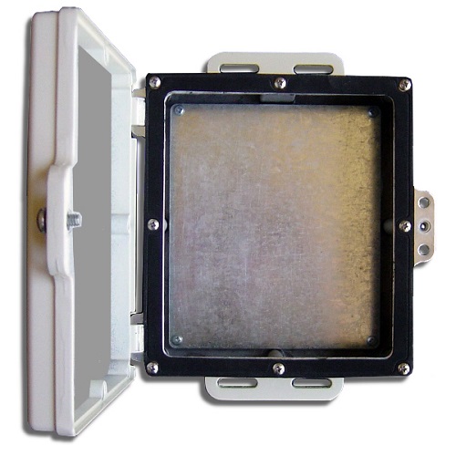
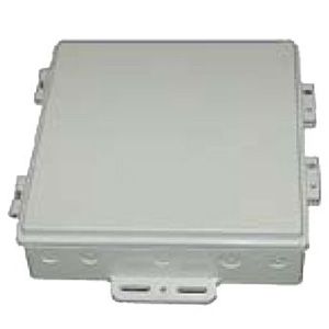
The enclosure is almost as important as the hardware it protects. Rfwel Engineering offers various pre-fabricated enclosures as well as custom-built enclosures to suite your mounting style, environmental conditions as well as your custom application hardware. Whether you need a NEMA-4+ enclosure with very custom requirements or just a simple indoor/outdoor enclosure, contact us and an enclosures expert will contact you with pricing and lead time. |
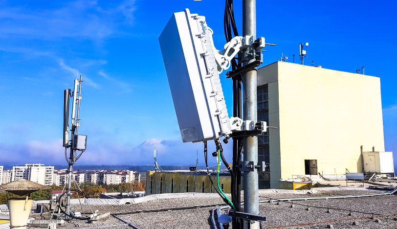 |
| We can customize your remote radio enclosure based on application and environmental hazards including encolures for harzadous environments. |
See below for popular enclosures or search for specific features using the enclosures filter: 
| Compare Equipment Enclosures Specs | ||
| Item | Key Specifications | Available at these Online Market Places |
|
Tycon Power Systems TPENC-DC-10x8x3 |
Size (Inches): 11 x 8.5 x 3.5 Internal Size (Inches): 10 x 7 x 3 Enclosure Construction: Die Cast, Aluminum, Powder Coated Weatherproofing: NEMA 4X, IP65 |
|
|
Tycon Power Systems TPENC-PL-14x10x5 |
Size (Inches): 17.5 x 12.5 x 6 Internal Size (Inches): 14 x 10 x 5 Enclosure Construction: Polycarbonate (PC) Weatherproofing: IP54 |
|
|
Laird Technologies LDDCE-H-7x6x2 |
Size (Inches): 10 x 7 x 2.3 Internal Size (Inches): 7 x 6 x 2 Enclosure Construction: Die Cast, Aluminum, Powder Coated Weatherproofing: IP67 |
|
|
Laird Technologies DCE10-H-001 |
Size (Inches): 12.3 x 11.5 x 3 Internal Size (Inches): 10 x 10 x 2 Enclosure Construction: UV Stabilized, ASA Weatherproofing: IP67 |
|
|
Laird Technologies DCE-7x6x2 |
Size (Inches): 10 x 7 x 2.25 Internal Size (Inches): 7 x 6 x 2 Enclosure Construction: Die Cast, Aluminum, Powder Coated Weatherproofing: IP67 |
|
|
Tycon Power Systems ENC-AL-65x18x20 |
Size (Inches): 69 x 20.5 x 25 Internal Size (Inches): 65 x 18 x 20 Enclosure Construction: Aluminum Weatherproofing: IP56 |
|
|
Tycon Power Systems ENC-PL-14x10x5 |
Size (Inches): 17.5 x 12.5 x 6 Internal Size (Inches): 14 x 10 x 5 Enclosure Construction: Glass Filled, Polycarbonate (PC) Weatherproofing: IP65, NEMA 4X |
|
|
Tycon Power Systems ENC-ST-23x14x12 |
Size (Inches): 24 x 15 x 14 Internal Size (Inches): 23 x 14 x 12 Enclosure Construction: Powder Coated, Steel Weatherproofing: IP65, NEMA 4X |
|
|
Tycon Power Systems ENC-STL-24x24x16 |
Size (Inches): 24 x 24 x 17.5 Internal Size (Inches): 23 x 23 x 16 Enclosure Construction: Powder Coated, Steel Weatherproofing: IP65, NEMA 4X |
|
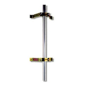
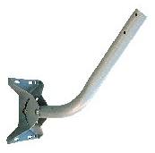
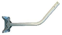
Antenna Towers & Mounts
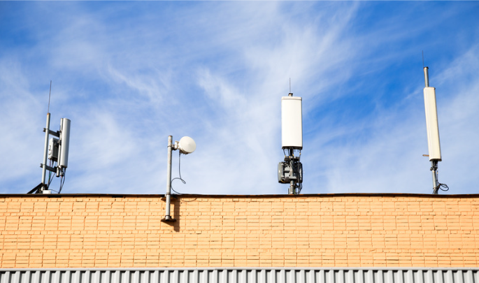
See below for popular towers and masts or search for specific features using the filter here: 
| Compare Antenna Towers & Masts Specs | ||
| Item | Key Specifications | Available at these Online Market Places |
|
Laird Technologies FMW4-YMST4 |
Type: Wall Mount Height: 4 ft. Diameter: 1.25 in. Standoff: 4 in. |
|
|
Laird Technologies JPIPE |
Type: J-Pipe Mount Height: 15 ft. Diameter: 1.5 in. Standoff: 10 in. Construction: Galvanized, Steel, Powder Coated |
|
|
Laird Technologies JPIPE-XL |
Type: J-Pipe Mount Height: 23 ft. Diameter: 1.5 in. Standoff: 14 in. Construction: Galvanized, Steel, Powder Coated |
|
|
Rohn FRM125HC |
Type: Roof Mount Height: 5 ft. Diameter: 1.25 in. Construction: Pre-Galvanized, Steel |
|
|
Rohn FRM225HC |
Type: Roof Mount Height: 5 ft. Diameter: 2.25 in. Construction: Hot-Dip Galvanized, Steel |
|
|
Rohn FRM238HC |
Type: Roof Mount Height: 2.5 ft. Diameter: 2.38 in. Construction: Hot-Dip Galvanized, Steel |
|
|
Baird WL2-36-237x3 |
Type: Wall Mount Height: 3 ft. Diameter: 2.37 in. Standoff: 36 in. |
|
|
Baird WL2-36-400x3 |
Type: Wall Mount Height: 3 ft. Diameter: 4 in. Standoff: 36 in. |
|


